SNEdge – SNES Image Sharpener Retro Game console Modified Accessory


SNEdge – SNES Image Sharpener Retro Game console Modified Accessory
Direkte levering: Dette produkt sendes direkte fra vores leverandør fra udlandet med AliExpress Selection Standard Shipping.
SPECIFICATIONS
Accessories Type: Leverless Controller
Brand Name: NONE
Choice: yes
Compatible Brand/Model: None
Electric: No
High-concerned chemical: none
Model Number: no
Origin: Mainland China
With USB: no
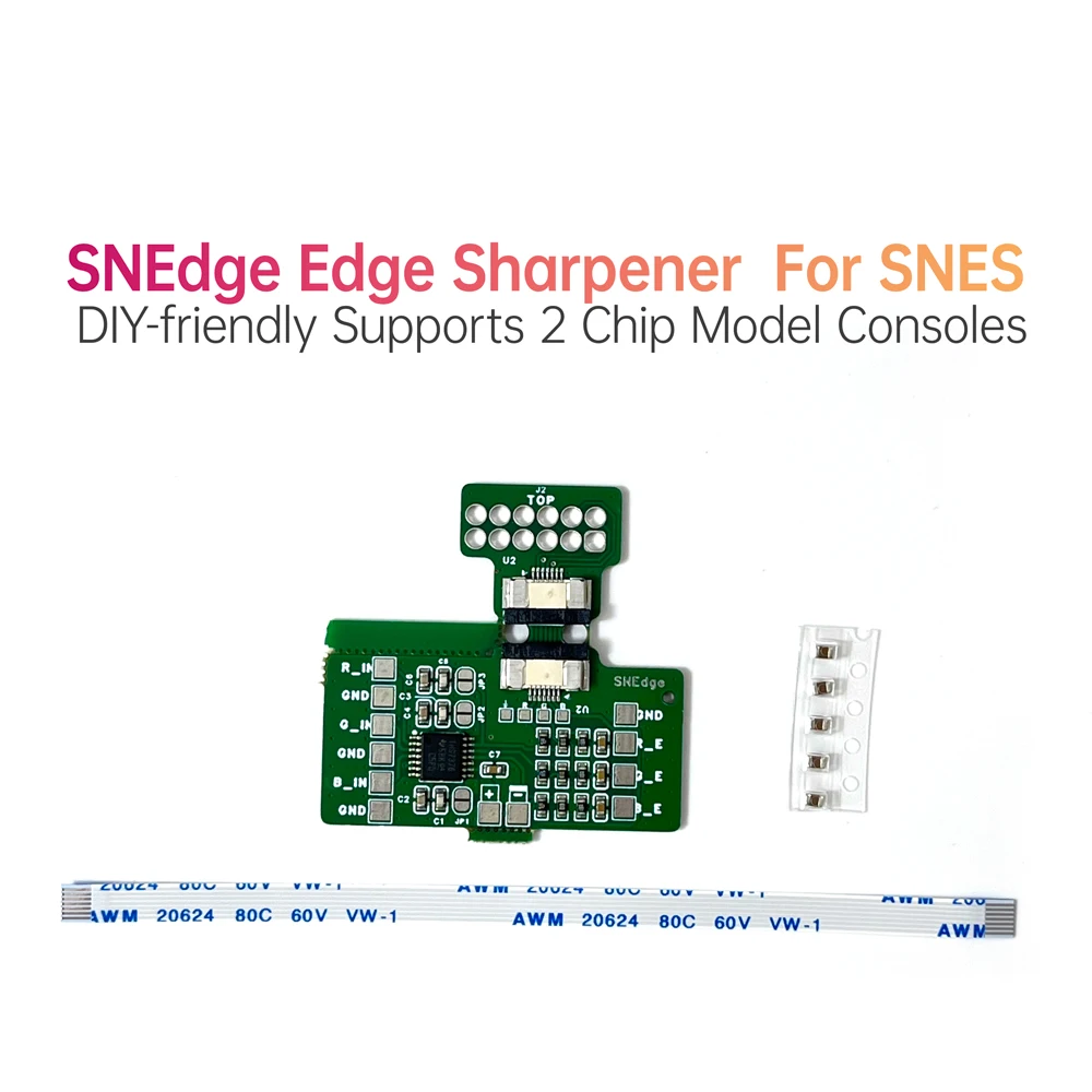
SNEdge - An Opensource SNES Edge Sharpener
You need to have some DIY soldering skills.
This is an Alpha version, supporting installation only on 2-chip model consoles. Later consoles such as Jr. and 1chip01/02/03 are not supported.
The SNEdge aims to correct much of the smearing that's present on the 2 chip SNES. Right now the SNEdge is a simple board that can be soldered to a SNES. This alpha version is designed to be installable on all revisions, as well as being relatively easy to solder since it uses 0805 components.
Installation Instructions
There are two methods of installation; Sidecar and RGB Bypass. The Sidecar install doesn't require any desoldering of components, but its sharpness isn't quite as good. The RGB Bypass has better sharpness, but is a more involved install.
For BOTH of these methods, it is absolutely critical so solder an additional 10uF capacitor onto C90, C91, C92, C93, and C94 on the SNES motherboard. If these caps aren't installed, the SNES's video output will be terribly noisy. (For PAL systems, it's C91, C92, C93, C94, and C95).
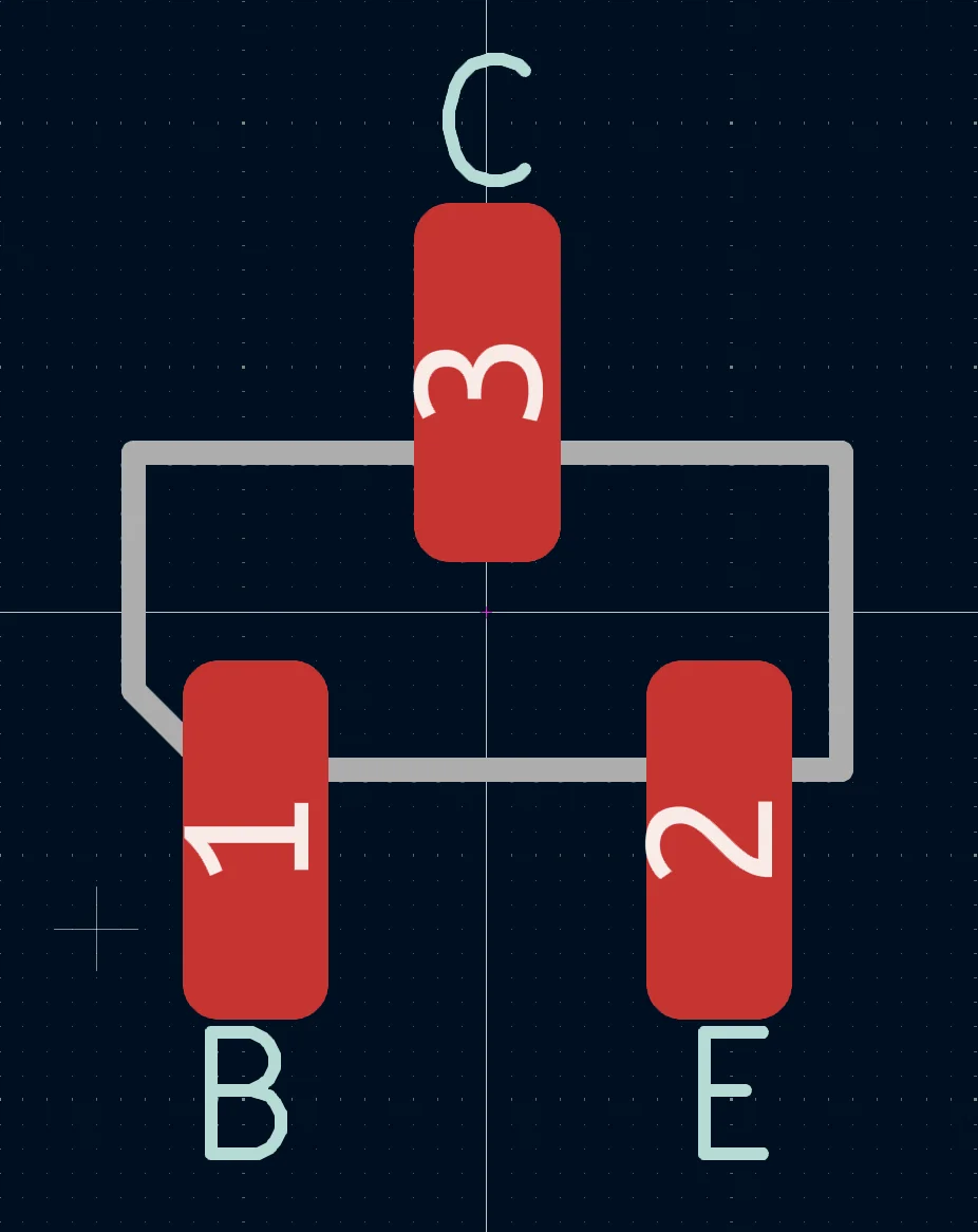
Below is an SOT-23 pinout I will be referencing later.
Sidecar Install
To start, solder JP1, JP2, and JP3 closed on the SNEdge.
Solder a 10uF cap on top of C90, C91, C92, C93, and C94. (For PAL systems, it's C91, C92, C93, C94, and C95).
Mount the SNEdge somewhere convenient (You'll want the RGB inputs to be as close as possible to Q3, Q5, and Q7).
Q3 is Red, Q5 is Green, and Q7 is Blue. Looking at the SOT-23 pinout above, pin 3 of each is ground. Pin 1 of each is the R, G, and B signals that will be soldered to the SNEdge.
Solder leads from Q3 to R_IN and GND.
Solder leads from Q5 to G_IN and GND.
Solder leads from Q7 to B_IN and GND.
NOTE: Each ground wire is important, don't skip out on this.
The SNEdge needs 5V. Solder 5V to the + and ground to the -
Again, don't skip on the ground, all of them are important.
That's it! You have completed the sidecar install.
Full RGB Bypass Install
If you're starting from a sidecar install, open JP1, JP2, and JP3. Otherwise, just leave them open. (Please note that PAL system installation is a bit different, I have info on this, and will be adding it eventually).
Solder a 10uF cap on top of C90, C91, C92, C93, and C94. (For PAL systems, it's C91, C92, C93, C94, and C95).
Mount the SNEdge somewhere convenient (You'll want the RGB inputs to be as close as possible to Q3, Q5, and Q7). Make sure that the FFC connector is pointed towards the multiout of the SNES.
Remove Q3, Q5, and Q7. If you only care about RGB working, remove R8, R9, R13, R14, R18, and R19. If you also care about Composite video and S-Video, also remove C6, C7, and C8.
Q3 is Red, Q5 is Green, and Q7 is Blue. Looking at the SOT-23 pinout above, pin 3 of each is ground. Pin 1 of each is the R, G, and B signals that will be soldered to the SNEdge.
Solder leads from Q3 to R_IN and GND.
Solder leads from Q5 to G_IN and GND.
Solder leads from Q7 to B_IN and GND.
NOTE: Each ground wire is important, don't skip out on this.
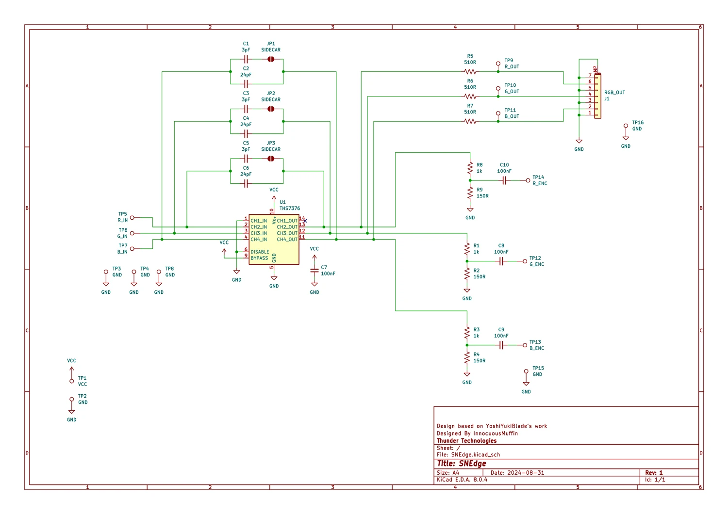
The SNEdge needs to output video to U7 (S-ENC) on the SNES in order for composite video and S-video.
The SNEdge R_E, G_E, and B_E outputs go to U7's pins 20, 21, 22 respectively. (you can ignore the GND pin next to these if you's like. If you care, connect it to pin 2 of U7.
Solder the multiout QSB on to the bottom of the SNES where the multiout pins are. If you're looking at the bottom of the SNES board, the "TOP" label on the QSB needs to be facing you, with the FFC connector pointing towards the SNEdge.
The SNEdge needs 5V. Solder 5V to the + and ground to the -
Connect the FFC cable to the SNEdge and the QSB. The contacts of the FFC face down, with the blue tabs facing up.
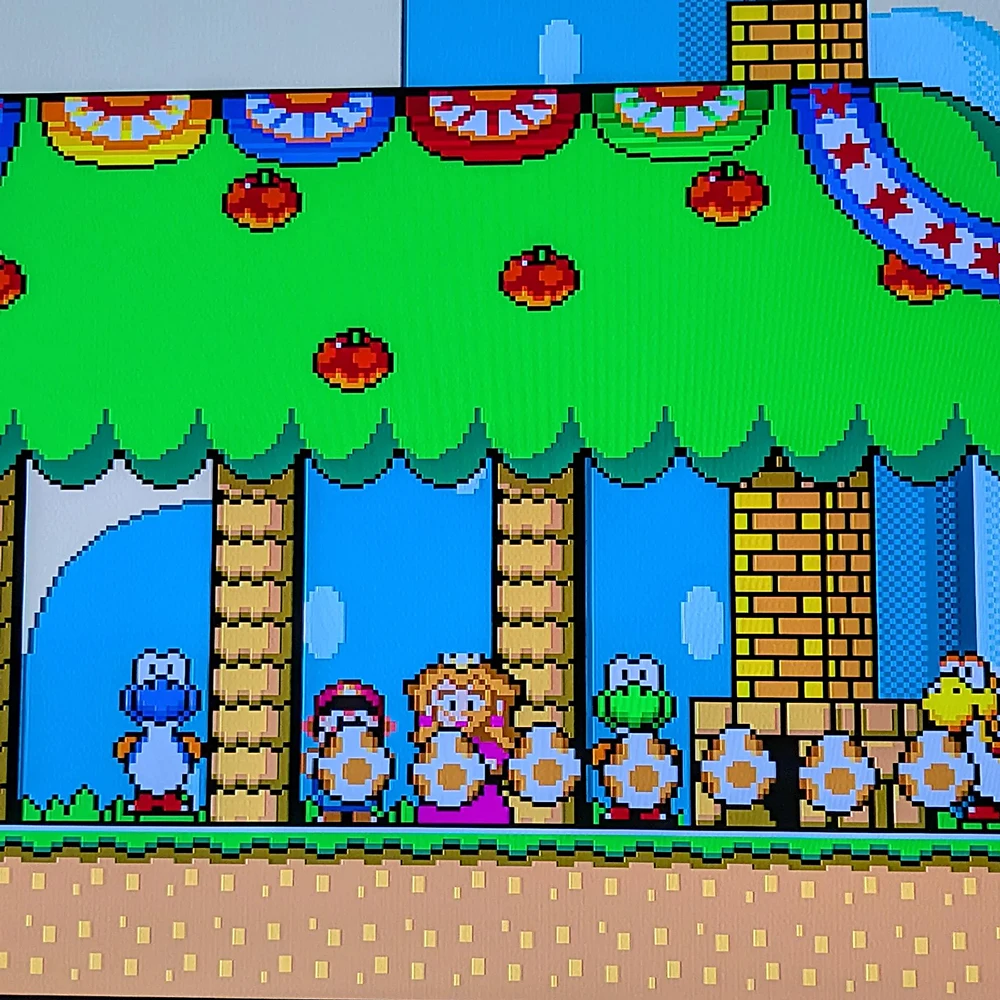
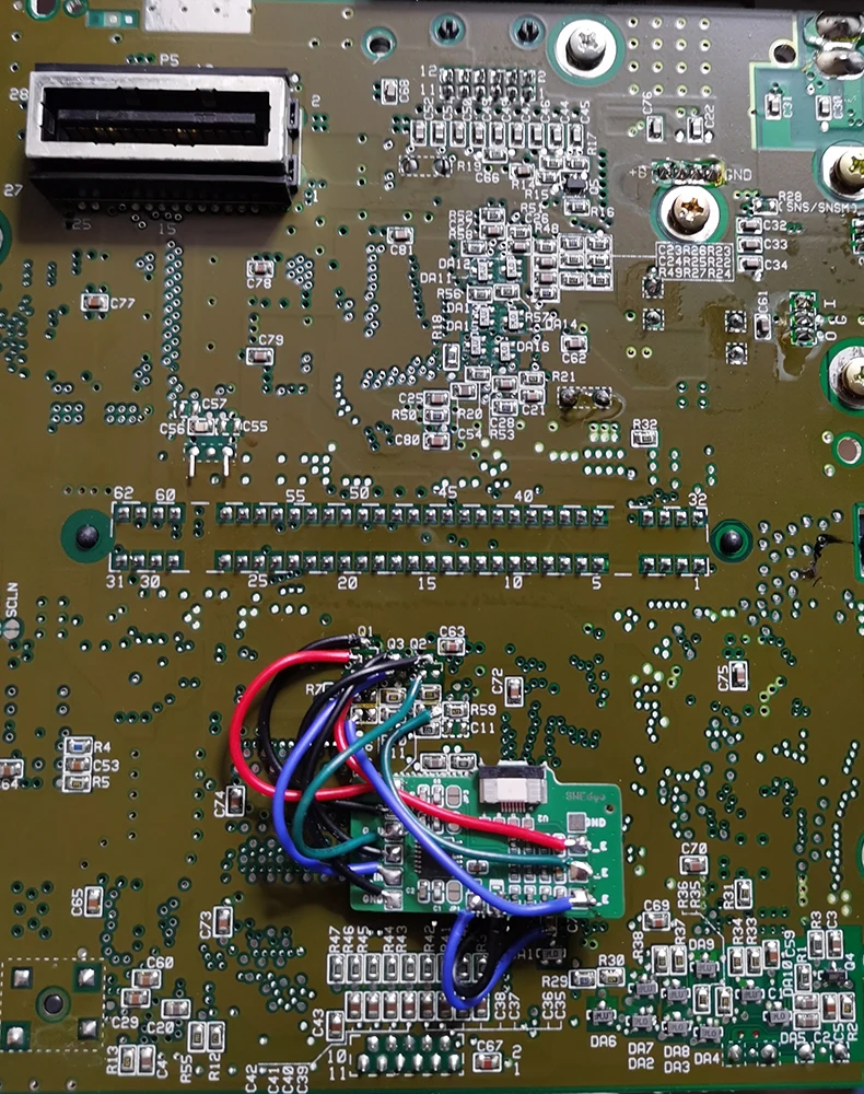
Installation Reference Diagram For CPU-01/02
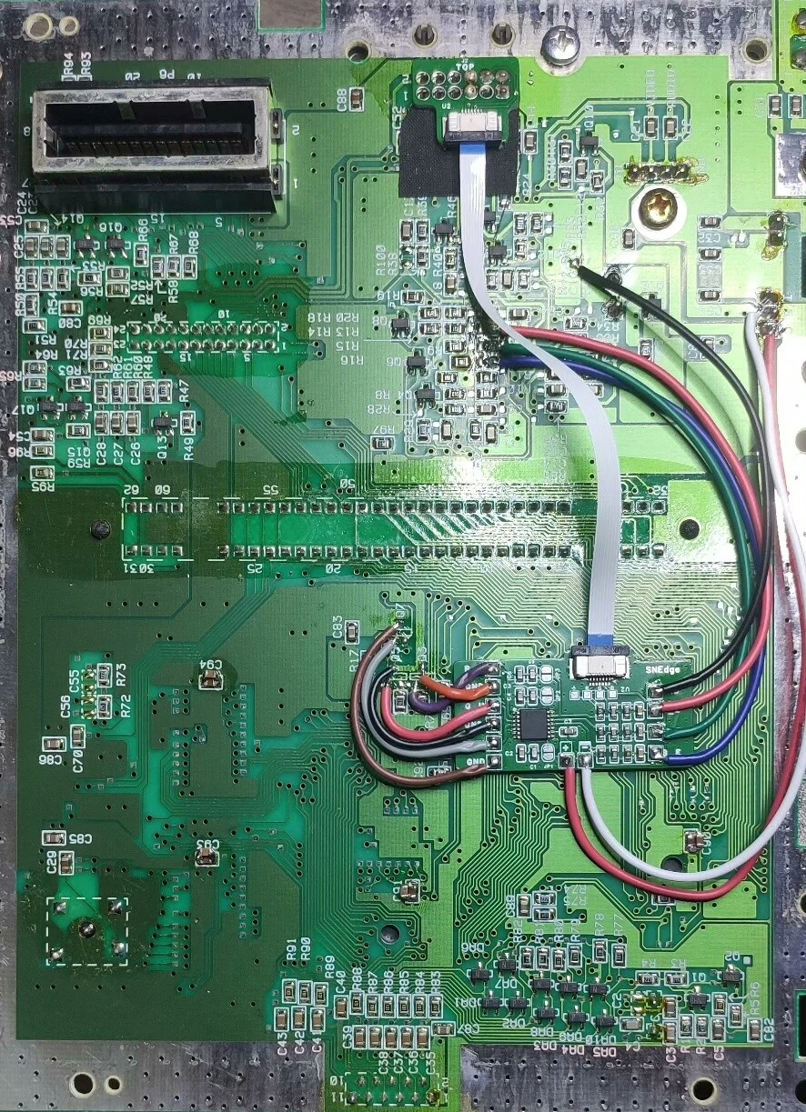
Installation Reference Diagram For RGB-01/02
For optimized installation, you can refer to other players' posts:
https://github.com/ThunderTechnologies/SNEdge/issues/6